Introduction
A two node multi-site
Windows failover cluster is typically used in non-production environments. The
key benefits of such an approach include providing a “cut down” replica of a
standard four-node failover cluster used in production and facilitating
simplified failover of services to disaster recovery sites.
In this architecture we
are deploying a single Windows server in both the primary and secondary sites.
These are clustered using Windows failover clustering. A quorum file server is
deployed (if one does not already exist) in the primary site to provide a third
“tie-breaker” node when it comes to voting on the primary node in the cluster.

Limitations
This approach provides a
solid disaster recovery failover solution however has the following
limitations:
i)
No high availability in the primary and / or
secondary sites. There is no option to failover to a secondary node in the
primary data centre.
ii)
Disaster recovery is a manual process. The
server node at the secondary site will only become the primary if both node A
fails and node B still has access to the quorum file server.
iii)
This guide is aimed at Windows Server 2016 and
Server 2019. Settings definitely need to be reviewed for older versions of
Windows.
Out of Scope
The following items are out of scope in this document. They
may be incorporated into future revisions.
i)
SQL Server Always On. This can be deployed on
top of the Windows failover cluster and should be treated as a separate work
item.
ii)
Shared storage – Not incorporated into this
document however may be added in future revisions.
iii)
Application resources and roles – Not
incorporated into this document however common roles may be added in future
revisions.
Pre-Build Checklist
Before building the
Windows failover cluster confirm the following details for the cluster:
Cluster Details
Cluster Name
|
|
Cluster Primary Site IP Address
The IP address for the
cluster at the primary site. This resolves to the Clustered Server Name
|
|
Cluster Secondary Site IP Address
|
|
Quorum File Share
Does a quorum file
server already exist or does one need to be created?
|
Server Node A Details
Server Node A Name
The name of the
server. This should be of the same format as the cluster name with A,B,C,or D
appended depending on which node this is in the cluster.
|
|
Server Node A Site
Enter the data centre code here
|
|
Server Node A Network
The network the server will be deployed into. Eg.
10.254.34.65/27
|
|
Server Node A IP Address
IP address of the server.
|
|
Server Node A vCPU
# vCPUs allocated to
this server. This should generally be 4 or lower. It should not exceed 8
without management approval.
|
|
Server Node A Memory
Server memory in GB.
|
|
Server Node A –
Disk C
Typically the standard 40GB unless otherwise
required.
|
|
Server Node A –
Disk E
Applications and
data drive
|
|
Server Node A –
Disk F
F drive typically reserved for SQL Server files.
Eg. Filestream, replication extracts
|
|
Server Node A –
Disk L
L drive typically
reserved for SQL Server Transaction Logs (LDF)
|
|
Server Node A –
Disk T
T drive typically
reserved for SQL Server tempdb (MDF and LDF)
|
Server Node B Details
Server Node B Name
The name of the server. This should be of the
same format as the cluster name with A,B,C,orD appended depending on which
node this is in the cluster.
|
|
Server Node B Site
Enter the data centre code here
|
|
Server Node B Network
The network the server will be deployed into. Eg.
10.254.34.65/27
|
|
Server Node B IP Address
IP address of the server.
|
|
Server Node B vCPU
# vCPUs allocated to
this server. This should generally be 4 or lower. It should not exceed 8
without management approval.
|
|
Server Node B Memory
Server memory in GB.
|
|
Server Node B –
Disk C
Typically the standard 40GB unless otherwise
required.
|
|
Server Node B –
Disk E
Applications and
data drive
|
|
Server Node B –
Disk F
F drive typically
reserved for SQL Server files. Eg. Filestream, replication extracts
|
|
Server Node B –
Disk L
L drive typically
reserved for SQL Server Transaction Logs (LDF)
|
|
Server Node B –
Disk T
T drive typically reserved for SQL Server tempdb
(MDF and LDF)
|
Cluster Quorum Server Build Process
If a quorum file server
does not already exist, one will need to be created. If one does exist, skip
this section and create the file share witness on the existing server.
Quorum File Server Build
·
Deploy a Windows Server as per the standard
server build process. Resource requirements are low with 2 vCPU and 2GB ram
being enough. A small secondary drive of 5GB is enough to host multiple quorum
file shares.
Create a quorums folder on the E drive of the server. (Note
screenshot shows C, this should be E)

Share this folder out.
The Windows share permissions are set to Everyone – Full Control.
Note that access to the share is restricted by NTFS.

On the NTFS Security
tab add the group ROL SEC Quorum Clients with Full Control.

Configure Active Directory Groups
In Active Directory if
the ROL SEC Quorum Clients group does not exist, create it. This group
will be used by computer server accounts to access the file share quorum.

In the group membership
add the computer accounts for the cluster and nodes to the group.


Cluster Build Process
Server Builds
·
Deploy Server Node A using the standard server
build process
·
Install the Failover Clustering feature
on Server Node A as shown in figure 1 below.
·
Reboot the server
·
Deploy Server Node B using the standard server
build process
·
Install the Failover Clustering feature
on Server Node B as shown in figure 1 below.
·
Reboot the server

Networking
Test Inter-Node RPC Connectivity
The Windows Failover
Clustering service on each node must have full communication with every other
node in the cluster over RPC. This occurs on TCP_135 but also my require high
or ephemeral ports in addition. Note that this may already be enabled on a per-zone
basis depending on the network implementation. To test connectivity between
nodes:
From Server Node A run:
telnet <server node B> 135
This should enter into a connection on
Server Node B.
From Server Node B run:
telnet <server node A> 135
This should enter into a connection on
Server Node A.
|
If either of these tests
fail troubleshoot connectivity between the two servers.
Test Quorum File share Connectivity
From Server Node A and
Server Node B run:
telnet <quorum file server>
445
This should enter into a
connection on the quorum file server.
VMWare Configuration
Anti-affinity rules are
configured in VMWare to ensure that two server nodes of a cluster do not reside
on the same physical host. If this was to occur an issue with the physical host
would impact more than one node in the cluster and cause an extended outage.
As this is a two-node
cluster with one server node per data centre this is not an issue and
anti-affinity rules do not need to be configured.
Configure Cluster
On the first Windows
failover cluster server node open Failover Cluster Manager:
Right click on Failover
Cluster Manager and click on Create Cluster…

This starts the wizard,
click Next.

Next add the server nodes
deployed in the Server Builds section to the cluster.

Now run the validation
tests. These tests are run to ensure that the hardware, operating system, and
software are all compatible with Windows Failover Clustering.


Select Run all tests
(Recommended)

Click Next to
continue.

Once complete the
interface should display The test passed. This is mandatory for some
applications such as SQL Server Always On which will refuse to install unless
the cluster validation checks pass.
As shown in the
screenshot below the test Validate Network Communication will report a
warning. This test will only pass if there are at least two network interfaces
on each node and the inter-node connectivity checks pass. This is OK as we’re using
high availability of the underlying network rather than at the operating system
level. The underlying network is not exposed to the operating system hence
Windows cannot confirm redundancy and reports the warning.

It should also be noted that a pass
for the Validate Network Communication does not always meet Microsoft
requirements. If a secondary network adapter in Windows shares common
infrastructure with the primary network adapter and that underlying
infrastructure is not highly available this will technical not be a valid
configuration.
|
Once the nodes have been
added and validation checks performed the cluster can be created. Enter the
cluster name and the IP addresses for the cluster itself. Note that the
screenshot below shows only one cluster IP address. In a multi-site
configuration, there will be one cluster IP address per site.

Click Next to
continue.

Click Finish to
complete creation of the cluster.

Cluster manager will now
show the newly created cluster. On the main dashboard we expect to see the
cluster server name and the cluster IP addresses online as shown below.

Under Nodes we’re
expecting to see each cluster node. Each node should be online with Status
Up.

Under Networks the
default setup should be correct. As we’re using a single network both the
cluster communications and clients should use the same network.

Disk I/O Timeout Configuration
VMWare recommend
increasing the Disk I/O timeout for Windows clusters. This is to make the
clustering less sensitive to vMotion events.
On each cluster node set
the disk I/O timeout to 60 seconds. Modify the registry key: HKEY_LOCAL_MACHINE\System\CurrentControlSet\Services\Disk\TimeOutValue.
Note that the system
might reset this I/O timeout value if you re-create a cluster.
Cluster HeartBeart
TimeOut
No modifications to the cluster heartbeat settings are
required for Windows Server 2016 and above. The best practice recommendations
for VMWare match the default values of Server 2016.
Cluster Service Accounts
No service accounts are created. Give the cluster computer
account permissions to read / write / create objects on the parent OU.
In ADUC ensure Advanced Features are shown.

Right click on the parent OU for the cluster and node
objects and select properties.
Add the cluster computer
account to the OU security. Ensure Read, Write, and Create all
child objects permissions are granted.
In the advanced security properties for the account ensure Create
Computer Objects permission is granted.

Cluster Quorum Configuration
Ensure the cluster and
server computer accounts have been added to the groups ROL SEC Quorum
Clients.
On the quorum file server
add a folder to the quorums share for this cluster. Note that this will inherit
the permissions

From the cluster
dashboard click on More Actions à
Configure Cluster Quorum Settings…


Select the option Select
the quorum witness.

Select Configure a
file share witness.

Add the full path of the
quorum file share as shown below. Make sure that the file share path terminates
into a dedicated folder for the cluster.
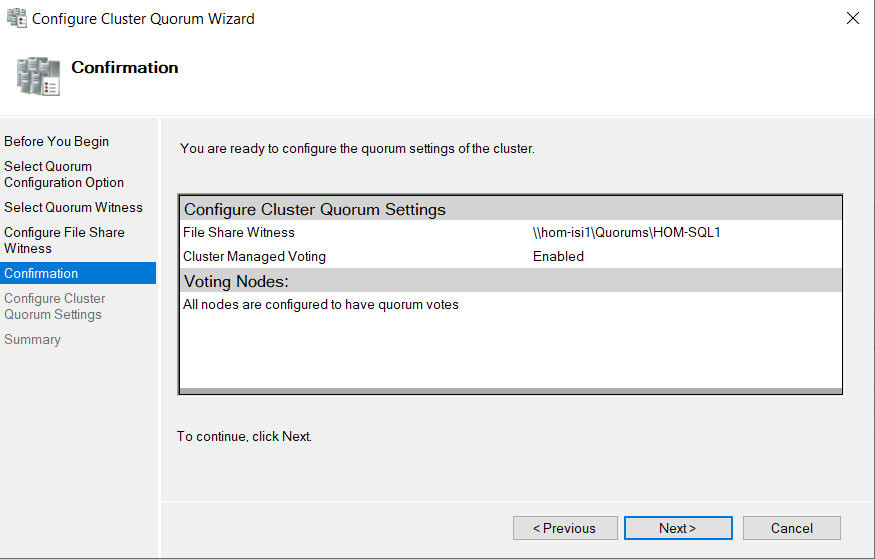
Click Next and Finish
to complete the quorum configuration.

Once the quorum creation
has finished check the file share. Two folders like the screenshot below should
be present in the folder indicating that the quorum file share is being used by
the cluster.

In the cluster dashboard
the File Share Witness should now be displayed as shown below.

Appendix A – References
Windows Failover Clustering Requirements
VMWare Windows Clustering
Cluster Heartbeat Settings
Appendix B – Design Considerations
Cluster Networking
Traditional cluster
networking involved two discrete networks on each cluster node, a private
network for cluster communications and a public network for application
traffic. Since Windows 2008 there is no such thing as a dedicated cluster
network. Instead Windows now probes the networking state to determine the
optimal network connection to send heartbeat traffic over meaning that the
heartbeat traffic can go over any network adapter available to Windows.
The recommendation is to
eliminate single points of failure in the network by either providing multiple
redundant networks to the Windows Server or by providing a single network
connection with full redundancy built in.
From the Microsoft
documentation:
In the network infrastructure that connects your cluster
nodes, avoid having single points of failure. There are multiple ways of
accomplishing this. You can connect your cluster nodes by multiple, distinct
networks. Alternatively, you can connect your cluster nodes with one network
that is constructed with teamed network adapters, redundant switches, redundant
routers, or similar hardware that removes single points of failure.
To maintain simplicity in
the environment the decision has been made to only use a single server network and
not implement a dedicated cluster network. As the cluster network makes use of
the same physical interface on the host and the same network fabric there is no
advantage in maintaining a dedicated cluster network.
Cluster Heartbeat
For a Windows Server 2016
and above failover cluster no changes to heartbeat settings are recommended.
Server 2016 implemented default settings in-line with VMWare recommendations
supporting vMotion and DRS.
No comments:
Post a Comment